What technologies can improve the accuracy of motor assembly lines?
1. System Architecture Overview
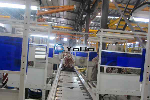
This assembly system features a modular segmented design comprising three core functional modules: the main conveyor line, workstation islands, and material handling subsystems. The primary transport mechanism is a heavy-duty slat conveyor, with deck width engineered to accommodate medium- to large-sized motor stator and rotor assemblies in stable transit. The load capacity per station aligns with the typical weight range of industrial-grade motors.
The line is flanked by enclosed workstation frames—white structural steel columns paired with blue protective panels that form semi-closed work zones. This configuration provides physical isolation for each station while preserving overhead clearance for crane-assisted loading, balancing operator safety with operational flexibility.
2. Conveyor System Engineering
2.1 Slat Conveyor Mechanics
Unlike light-duty belt or roller conveyors, this system uses a metal slat chain drive. Individual slats are joined by precision hinges to form a rigid, continuous conveying surface. This design delivers several key advantages:
- Superior off-center load resistance: Stator and rotor assemblies with asymmetric centers of gravity remain stable during transport without lateral shift or tipping.
- High impact durability: The system resists wear from incidental contact with assembly tools or components.
- Precise indexing capability: Fixed slat pitch combined with pneumatic stop cylinders achieves station stopping accuracy within ±2 mm.
Conveyor speed is governed by a variable-frequency drive (VFD), enabling dynamic adjustment—speeding up during idle segments and slowing or pausing at active workstations, with cycle timing synchronized to actual process duration.
2.2 Workstation Layout Logic
The line is sequenced according to the motor assembly process flow:
| Zone | Core Operation | Process Highlights |
|---|---|---|
| Load‑in | Stator insertion, frame positioning | Crane‑assisted lift, manual rough alignment |
| Assembly | Rotor insertion, bearing press‑fit, end‑shield fastening | Torque‑controlled fastening, interference‑fit monitoring |
| Inspection | Leak testing, insulation resistance, rotation check | In‑line automated testing, data traceability |
| Load‑out | Product labeling, protective packaging, pallet return | Auto‑labeling, empty pallet recirculation |
Station spacing is optimized using bottleneck‑analysis‑based golden‑section allocation, ensuring balanced material flow and preventing work‑in‑process (WIP) accumulation.
3. Auxiliary Process Equipment
3.1 Overhead Bridge Crane System
The plant ceiling is equipped with single‑girder bridge crane rails spanning the entire line. The crane and conveyor operate as a coordinated 3D system:
- The conveyor manages horizontal process flow.
- The crane handles vertical loading of heavy components.
Both systems are synchronized via floor‑level dispatch commands. The crane pre‑positions components before they reach the load‑in station, eliminating dwell time.
3.2 Workstation Environment
Each workstation island is equipped with:
- Adjustable task lighting: Directional lighting for shadowed areas such as motor internal cavities.
- Tool suspension systems: Pneumatic wrenches, press‑fit fixtures, and auxiliary tools positioned within ergonomic reach according to motion‑economy principles.
- Visual error‑proofing aids: Photoelectric sensors at critical stations trigger automatic alerts for missing components.
4. Quality Control Gates
Quality assurance is enforced at three hierarchical levels:
Level 1: Incoming Material Pre‑Inspection
At the load‑in station, stator winding insulation resistance and frame locating bore dimensions undergo rapid verification. Non‑conforming parts are diverted before entering the main line.
Level 2: In‑Process Monitoring
The bearing press‑fit station includes force–displacement curve monitoring, with real‑time comparison against standard process windows. End‑shield bolt fastening uses intelligent electric nutrunners with closed‑loop torque and angle control; data is automatically bound to the motor serial number.
Level 3: Final Inspection
Finished motors undergo full‑parameter testing at the inspection zone—no‑load current, vibration severity, and temperature rise—with reports auto‑archived for batch or unit‑level traceability.
5. Application Scenarios
This assembly line is designed for the following manufacturing requirements:
- Medium‑ to large‑size low‑voltage motors: Power range 11 kW to 315 kW, frame sizes 160 to 400.
- High‑mix, batch‑style production: Quick‑change tooling enables flexible changeover across different frame sizes.
- Stringent quality traceability: Automatic data capture at every operation meets ISO quality‑management system requirements.
6. Conclusion
Heavy‑duty motor assembly extends beyond simple component stacking—it is a multidimensional convergence of mechanical precision, electrical performance, and thermal dynamics. A well‑designed assembly line delivers value not only through transport efficiency, but by decomposing complex assembly tasks into repeatable, measurable, and optimizable standard work units.
From the robust load‑bearing capacity of the slat conveyor, to station‑level process error‑proofing, to plant‑wide data integration, this system establishes a complete closed‑loop assembly process. It provides the foundational infrastructure for scaling motor manufacturing while maintaining the precision required for high‑reliability industrial products.